- MODULE 1 -
NETWORK REPRESENTATIONS
Network Interface Card - A NIC, or LAN adapter, provides the physical connection to the network at the PC or other host device. The media connecting the PC to the networking device plugs directly into the NIC.
Physical Port - A connector or outlet on a networking device where the media is connected to a host or other networking device.
Interface - Specialized ports on an internetworking device that connect to individual networks. Because routers are used to interconnect networks, the ports on a router are referred to network interfaces.
 NETWORK TOOL
traceroute <destination network name or end device address>
(Unix and similar systems)
or
tracert <destination network name or end device address>
(MS Windows systems)
TYPES of PHYSICAL MEDIA
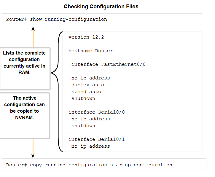
CONFIGURATION FILES
A Cisco network device contains two configuration files:
The
running configuration file - used during the current operation of the device
The
startup configuration file - used as the backup configuration and is loaded when the device is started
A configuration file may also
be stored remotely on a server as a backup.
- Interface mode - to configure one of the network interfaces (Fa0/0, S0/0/0,..)
# interface serial 0/0/0
- Line mode - to configure one of the lines (physical or virtual) (console, AUX, VTY,..)
# line console 0
- Router mode - to configure the parameters for one of the routing protocols
#router rip
VTY Password
The vty lines allow access to a router via Telnet.
By default, many Cisco devices support five VTY lines that are numbered 0 to 4.
Encrypting Password Display
Another useful command prevents passwords from showing up as plain text when viewing the configuration files.
This is the
service password-encryption command.
The following example reloads the software on the router in 10 minutes:
Router# Reload scheduled for 11:57:08 PDT Fri Apr 21 1996 (in 10 minutes)
Proceed with reload? [confirm]
The following example reloads the software on the router at 1:00 p.m. today:
Router# Reload scheduled for 13:00:00 PDT Fri Apr 21 1996 (in 1 hour and 2 minutes)
Proceed with reload? [confirm]
The following example reloads the software on the router on April 20 at 2:00 a.m.:
Router# reload at 02:00 apr 20
Router# Reload scheduled for 02:00:00 PDT Sat Apr 20 1996 (in 38 hours and 9 minutes)
Proceed with reload? [confirm]
The following example cancels a pending reload:
%Reload cancelled.
VERIFY CONNECTIVITY
IOS Ping Indicators

A ping from the IOS will yield to one of several indications for each ICMP echo that was sent. The most common indicators are:
! - indicates receipt of an ICMP echo reply
. - indicates a timed out while waiting for a reply
U - an ICMP unreachable message was received
User EXEC Mode
enable - Enter Privileged EXEC mode
Privileged EXEC Mode
copy running-config startup-config - Copy the active configuration to NVRAM.
copy startup-config running-config - Copy the configuration in NVRAM to RAM.
erase startup-configuration - Erase the configuration located in NVRAM.
ping ip_address - Ping to that address.
tracerouteip_address - Trace each hop to that address.
show interfaces - Display statistics for all interfaces on a device.
show clock - Show the time set in the router.
show version - Display currently loaded IOS version, hardware, and device information.
show arp - Display the ARP table of the device.
show startup-config - Display the saved configuration located in NVRAM.
show running-config - Display the contents of the currently running configuration file.
show ip interface - Display IP statistics for interface(s) on a router.
configure terminal - Enter terminal configuration mode.
Terminal Configuration Mode
hostname hostname - Assign a host name to device.
enable passwordpassword - Set an unencrypted enable password.
enable secret password - Set a strongly encrypted enable password.
service password-encryption - Encrypt display of all passwords except secret.
banner motd# message # - Sets a message-of-the-day banner.
line console 0 - Enter console line configuration mode.
line vty 0 4 - Enter virtual terminal (Telnet) line configuration mode.
interface Interface_name - Enter interface configuration mode.
Line Configuration Mode
login - Enable password checking at login.
password password - Set line password.
Interface Configuration Mode
ip addressip_address netmask - Set interface IP address and subnet mask.
description description - Set interface description.
clock rate value - Set clock rate for DCE device.
no shutdown - Set interface to up.
shutdown - Administratively set interface to down.
Cisco Router and Switch IOS Password Recovery
http://www.cisco.com/warp/public/474/pswdrec_1700.pdf
http://www.cisco.com/warp/public/474/pswdrec_2900xl.pdf
The typical hierarchical design model is broken up in to three layers:
- access : The access layer can include routers, switches, bridges, hubs, and wireless access points.The main purpose of the access layer is to provide a means of connecting devices to the network and controlling which devices are allowed to communicate on the network.
- distribution : The distribution layer controls the flow of network traffic using policies and delineates broadcast domains by performing routing functions between virtual LANs (VLANs) defined at the access layer. VLANs allow you to segment the traffic on a switch into separate subnetworks. For example, in a university you might separate traffic according to faculty, students, and guests. Distribution layer switches are typically high-performance devices that have high availability and redundancy to ensure reliability.
- core : The core layer of the hierarchical design is the high-speed backbone of the internetwork. The core layer is critical for interconnectivity between distribution layer devices, so it is important for the core to be highly available and redundant. The core area can also connect to Internet resources. The core aggregates the traffic from all the distribution layer devices, so it must be capable of forwarding large amounts of data quickly.
An example of a three-layer hierarchical network design is displayed in the figure.


 ANALYSIS TOOLS
Traffic flow analysis is the process of measuring the bandwidth usage on a network and analyzing the data for the purpose of performance tuning, capacity planning, and making hardware improvement decisions. Traffic flow analysis is done using traffic flow analysis software.
Many traffic flow analysis tools that automatically record traffic flow data to a database and perform a trend analysis are available. In larger networks, software collection solutions are the only effective method for performing traffic flow analysis.
The figure displays sample output from
Solarwinds Orion 8.1 NetFlow Analysis, which monitors traffic flow on a network. While the software is collecting data, you can see just how every interface is performing at any given point in time on the network. Using the included charts, you can identify traffic flow problems visually. This is much easier than having to interpret the numbers in a column of traffic flow data.
For a list of some commercial traffic flow collection and analysis tools, visit
http://www.cisco.com/warp/public/732/Tech/nmp/netflow/partners/commercial/index.shtml
For a list of some freeware traffic flow collection and analysis tools, visit
http://www.cisco.com/warp/public/732/Tech/nmp/netflow/partners/freeware/index.shtml
 SWITCH FEATURES
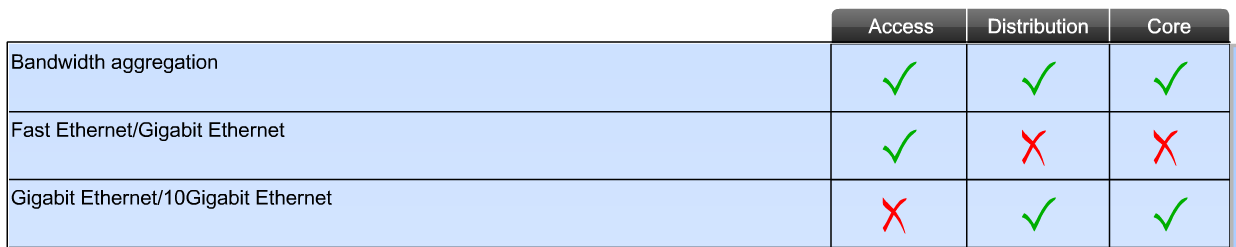
Two other characteristics you want to consider when selecting a switch are
:
- Power over Ethernet (PoE)
- Layer 3 functionality

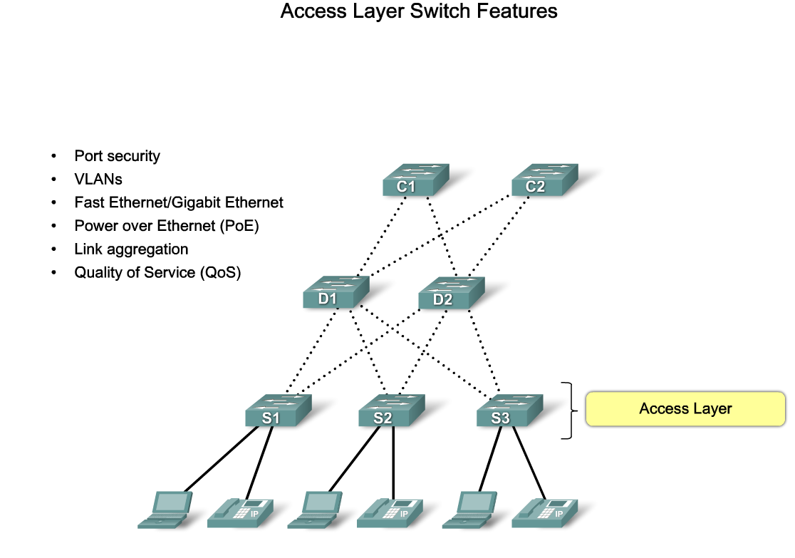
 Access layer : switches facilitate the connection of end node devices to the network.
For this reason, they need to support features such as port security, VLANs, Fast Ethernet/Gigabit Ethernet, PoE, and link aggregation.
Distribution layer
Access layer : switches facilitate the connection of end node devices to the network.
For this reason, they need to support features such as port security, VLANs, Fast Ethernet/Gigabit Ethernet, PoE, and link aggregation.
Distribution layer: switches provides the inter-VLAN routing functions so that one VLAN can communicate with another on the network.
This routing typically takes place at the distribution layer because distribution layer switches have higher processing capabilities than the access layer switches.
Distribution layer switches alleviate the core switches from needing to perform that task since the core is busy handling the forwarding of very high volumes of traffic.
Because inter-VLAN routing is performed at the distribution layer, the switches at this layer need to support Layer 3 functions.
Core layer: is the high-speed backbone of the network and requires switches that can handle very high forwarding rates.
The required forwarding rate is largely dependent on the number of devices participating in the network. You determine your necessary forwarding rate by conducting and examining various traffic flow reports and user communities analyses.
Based on your results, you can identify an appropriate switch to support the network. Take care to evaluate your needs for the present and near future.
If you choose an inadequate switch to run in the core of the network, you face potential bottleneck issues in the core, slowing down all communications on the network.
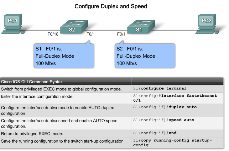
CISCO CATALYST SWITCH:
- auto option sets autonegotiation of duplex mode.With autonegotiation enabled, the two ports communicate to decide the best mode of operation.
- full option sets full-duplex mode
- half option sets half-duplex mode
Additionally:
- mdix auto When the auto-MDIX feature is enabled, the switch detects the required cable type for copper Ethernet connections and configures the interfaces accordingly. Therefore, you can use either a crossover or a straight-through cable for connections to a copper 10/100/1000 port on the switch, regardless of the type of device on the other end of the connection.
The auto-MDIX feature is enabled by default on switches running Cisco IOS Release 12.2(18)SE or later. For releases between Cisco IOS Release 12.1(14)EA1 and 12.2(18)SE, the auto-MDIX feature is disabled by default.
SWITCH SECUTIRY PASSWORD